
BS2-OEM ‘LITE’ [BS2]
The BASIC Stamp Microcontroller can reduce the development time of many applications and therefore is a popular platform for both beginners and intermediate developers. However the cost of the BASIC Stamp Microcontroller Modules can be cost prohibitive in volume applications.
History
BASIC Stamp Microcontrollers are the heart of many commercial and private devices around the world. They’re used in more places than you might think or even know about. I have used them myself in a good many projects, including some commercial applications. But circuit designers and engineers who build around them are often faced with a cost dilemma when they come up with something that will be manufactured in quantity. At this point $29.00 for a BS1 module up to $89.00 for a BASIC Stamp 2p40 module becomes cost-prohibitive.
Many find it hard to choose between the ease of development provided by the BASIC Stamps and the lower cost of harder to use microcontrollers. The real issue is in using the module itself in final products. BASIC Stamp modules are hybrid microcontrollers made up of many smaller groups of circuits. Besides the necessary components for running the controller itself (interpreter, resonator and EEPROM) it also contains a voltage regulator, brownout detector and RS-232 interface circuitry. Add to that, this is all surface mounted into a 24-pin DIP package with special press-fit lead-legs and the result is that the module is going to become very costly to make.
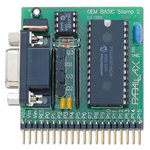
The modules themselves are really meant more for development and are also useful in an educational role. For production use the real savings in cost is integrating the BASIC Stamp core into your design directly. Parallax originally provided the OEM-BS1, OEM-BS2 (shown to the left) and OEM-BS2sx as an example of the components that make up a BASIC Stamp module in through-hole form. Some hobbyists use the OEM kit in their designs but many don’t need the part count overhead of the complete design.
BASIC Stamps, Simplified
The minimum required components for a functioning BASIC Stamp microcontroller are the interpreter, resonator and EEPROM. With the exception of a few resistors, everything else on the module is support circuitry. Some of this circuitry may already be a part of your own design, such as the voltage regulator. Other circuitry may not be required in your application, for example you may not need the programming interface in your system. You can always update code / firmware by swapping out the EEPROM.
In these cases the parts count of integrating the BASIC Stamp can be reduced significantly. In my last commercial design the cost of integrating a BASIC Stamp went from $89.00 (the cost at the time for a BS2p40) to just under $15.00 and I retained the ability to field program the device using a USB interface by Parallax called USB2SER, connected as-needed to a 4-pin header on the board.


The three schematics shown are modified versions of the original schematic for the OEM-BS2 from Parallax Inc. The OEM-BS2 uses all through-hole parts. Please note that the through-hole and SMD versions of the interpreter may have different pinouts. This is very important as I have seen a few people make the mistake of laying out an SMD PCB design using the pinouts in this schematic. You have been warned.
OEM-BS2 LITE
This schematic was the first one I used in a customer application. It removes all the RS-232 support circuitry and replaces it with a single diode. By doing this you retain the ability to field program using the USB2SER while minimizing component count. This schematic retains the brown-out detector as well and also shows the 5V regulator. These may not be necessary in your application further reducing part count.
Version 2
If you have no need for field programming then you can use this version of the schematic, which removes all programming functionality and provides you with a fully functional BASIC Stamp 2. Once again, the regulator is probably already included in your application and can be left out of this schematic as well.
Version 3
This version goes one step further from the previous one by removing the brown-out detector. While not necessary for the BASIC Stamp to function, the brown-out detector protects the BASIC Stamp EEPROM from getting corrupted when voltage falls below the minimum supply voltage required by the EEPROM. It does this by holding the BASIC Stamp in a state of reset when the system voltage falls below that set by the brown-out detector. This way the EEPROM is not written to and potentially corrupted.
Other Information
If you’re using a low-voltage version of the EEPROM (many are these days) the brown-out detector becomes less critical as the interpreter will fail to function before the EEPROM. Note that the pin numbers may vary on your brownout detector. Always consult the datasheet before connecting any component to be sure your pinouts match the schematic. Also note whether the pinout diagram is top-view or bottom-view. The principles here easily carry over to other models of the BASIC Stamp besides the BS2.
Revised (01-14-2012)
Recently I dragged out this tutorial for someone and realized it was getting on in age. At the time I wrote it, I simply took the original schematic image and used a paint program to cut out sections of the circuit I did not need in my application, whittling more and more away until I had three versions of the circuit as in the original images above. However, from the base circuit there are two optional sections of the circuit that I felt weren’t made very clear in my hacked images from before. I had also built more OEM circuits since the original and wanted to share some new information.
Recent Testing
At some point the prices changed on the modules and the OEM components forcing me to revisit the price issue with a Parallax customer. In the process of revisiting things it turned out the BS2e interpreter was now less expensive than the BS2 interpreter and had more functions and memory. So I built both configurations side-by-side on a RadioShack breadboard to do a little testing. Interestingly the BS2 and BS2e both fit on the same breadboard at the same time with just enough room for a single heartbeat status LED for each, connected to P15 on both BASIC Stamp Microcontrollers.


The smaller breadboard shown in the Revised Prototype photo above was used to hold the optional programming circuitry to allow the BASIC Stamp to be reprogrammed via a Prop Plug from Parallax Inc. The Prop Plug is typically used to program a Propeller chip microcontroller, also by Parallax, however in its simplest form it is a USB to Serial interface which, with only a 4.7K resistor and a diode can be used to program an OEM BASIC Stamp like the ones in the photos above. A closer view shows just how tightly everything fits on this breadboard, yet we have two complete functioning BASIC Stamp microcontrollers with minimal components required to run them.
Overview of Revised Schematic
U1 is the BASIC Stamp Interpreter chip from Parallax Inc. While this IC is a Microchip PIC16F57, it must have Parallax’s proprietary firmware installed on it to make a BASIC Stamp. A blank PIC chip won’t work. Interpreter chips can be purchased in through hole and SMD directly from Parallax Inc. The interpreter requires a 20MHz resonator to run. This resonator can be purchased from Parallax, as can the 10K feedback/drive resistor (R1), reset pull-up (R2) and SIN pull-up (R4). In fact all the parts used here can be purchased from Parallax except the diode which can be picked up at RadioShack. But honestly, who doesn’t have a 1N914 or equivalent diode laying around their bench or in a parts cabinet?!?


U1 is certainly the heart of the microcontroller, however BASIC code is not stored on the PIC chip, but rather on an external IC. Enter U2, which is a 24LC16B 2K EEPROM. The I2C interface requires a 4.7K resistor (R3) on the SDA line. Other than a clean 5V power source you have the minimal components required for a fully functional BASIC Stamp 2 Microcontroller. Note that the BS2E and BS2SX version use a larger EEPROM, since they have multiple banks of memory. The BS2SX version also uses a 50MHz resonator, instead of the 20MHz resonator used by the BS2 and BS2E versions.
Options
There are two optional sections of the schematic. The brownout detector (U3) and the Prop Plug programming circuit (J1, R5 and D1). The brownout detector prevents the EEPROM from being corrupted in the event of a brownout on the power supply or low batteries. It does this by holding the /RESET line low whenever the supply voltage drops below 4.2V. The Prop Plug interface allows you to field program your BS2-OEM using a Prop Plug. The 4-pin connector (J1), echo resistor (R5) and diode (D1) can be integrated into your board if you need field programming. Or you can design a custom programming interface that adds these components to the Prop Plug circuitry.
What about a 3.3V BASIC Stamp?
A 3.3V BASIC Stamp? It sure is possible since the interpreter and EEPROM chips run at voltages below 3.3V. On top of that the firmware assumes an external brownout detector so the internal one is not enabled on the interpreter. Because of this you can power this circuit from 3.3V with one caveat…you will need to remove R1 from the resonator. The value of R1 was chosen based on a 5V circuit, however at 3.3V the resistor is too low of a value. I haven’t tested for the optimum value yet, however removing the resistor seems to allow the resonator to function at 3.3V. Still, I cannot guarantee the temperature range the circuit will operate under these circumstances. I would also recommend the brownout circuit when running at 3.3V, though you will need to get a 2.8V version of the voltage detector.
Conclusion
The attached ZIP file contains high-resolution schematics for the BS2-OEM, BS2e-OEM and BS2sx-OEM. The concepts applied here can be used on any BASIC Stamp Model, but beware of the pinouts of the interpreter IC. Through hole and SMD versions quite often have different pinouts. Also, the “brownout detector” is also known as a “voltage detector”. Please note that as of 1-30-2021, Parallax is only selling the interpreter chips for the BS1 and BS2. They have also discontinued several models of the BASIC Stamp Modules.
Resources
Arduino OEM [Arduino] – Tutorial
BS2-OEM ‘LITE’ by Chris Savage is licensed under CC BY 4.0![]()
![]()
