
BASIC Stamp Module Tester
This easy to build and use tester will allow you to test your BASIC Stamp Modules (any model) for bad I/O pins, RAM and other issues that may cause problems in your projects. This tester only works on BASIC Stamp microcontrollers that can still communicate with the PC and cannot test modules that are completely dead (bricked).
History
BASIC Stamp microcontrollers are one of the most well known microcontrollers out there. That popularity is well deserved and includes vast amounts of free documentation and example code as well as free technical support and web based resources such as a support/discussion forums. Parallax takes great pride in manufacturing these microcontrollers here in the USA and every BASIC Stamp manufactured is fully tested before being sold. This procedure is done one BASIC Stamp at a time, usually in lots of 50, 100 or more. Over time Parallax has developed and improved the testing of BASIC Stamps. Originally there were separate programs and test boards for each BASIC Stamp model. My goal was to have one board and source code to handle all the testing.
To that end I worked with Senior Application Engineer Jeff Martin to not only simplify the test procedure for manufacturing, but make it better and to be able to detect more possible types of problems discovered in my time in Parallax Tech Support. While the code was being improved I created a test board that could handle any BASIC Stamp Module. This includes the BS1 and all 24 and 40-pin BASIC Stamp 2 models. Parallax has allowed me to release the code and plans for this board to our customers as well as another tester I built for the exceptions…the exceptions being boards like the HomeWork Board, Sumo Board and Toddler Board where the BASIC Stamp is surface mounted and cannot be removed to plug into this test board. First I’ll cover the test board, then the card tester.
ExpressPCB is Fast & Easy


I needed the board in a hurry and I already had a reference schematic so I used ExpressPCB to quickly create the PCB you see. Using the mini-board service we got three of these for under $60.00 in 3 days. The ExpressPCB file can be downloaded at the end of this article (ZIP file attachment). As you can see from the solder side of the board all ground connections are part of the ground plane.
Assembly Time
For me populating the PCB begins with the smaller components. I do this to make it easy to solder sockets and resistors while being able to lay the board down flat on a surface. Once the smaller components are in then I start working my way up.

Parts: (1) 14-pin and (2) 20-pin machined sockets. The 14-pin socket mounts on the left side of the board as shown. The two 20-pin sockets on the right need to line-up with the ZIF socket in the end so I plugged the socket in until I got these fully soldered in, then removed the ZIF socket for the rest of the assembly.

Parts: (1) 3-pin RA SIP Header, (8) 4.7K resistors and (2) 470Ω resistors. 3-Pin RA SIP header mounts on the far left. This is where the BS1 Serial Adapter connects. The 4.7K resistors run from the bottom-right of the BS1 socket about half way up. These are connected to the BS1 I/O pins. The 470Ω resistors mount above the 4.7K resistors and control current to the LEDs.
Note: These (values) may be changed as needed for the color LEDs you use.

Parts: (8) .01µF capacitors, (34) .1µF capacitors and (1) Tact Switch.
The eight .01µF capacitors (marked 103) install just to the right of each 4.7K resistor. 32 of the .1µF capacitors (marked 104) install down either side of where the 40-pin ZIF socket will install. The other two install just below where the DB-9 mounts. Note the orientation of these two as it differs from the others (vertical rather than horizontal). The RESET switch mounts bottom center of the board and should only fit one way.

Parts: (4) 10K SIP resistor packs and (2) LEDs (any color). The 10K SIP resistor packs should have a dot or line to signify pin 1. This is very important as these are bussed and have a common ground pin which must be at the square pad on each of the four areas they mount. The LEDs can also be mounted. Color does not matter and you can always use two of the same color if you want.

Parts: (1) DC power jack and (1) DB-9 RA serial connector. Mounting holes for the DC power jack are slightly large on the units I have. Be advised that you should exercise caution installing this unit because you’ll need a lot of solder, but you don’t want to melt the connector or damage the PCB from excessive heat. The DB-9 should snap right in. I only put a little bit of solder around the mounting tabs since they practically lock in place anyway. The solder there is more to keep the tabs from unlocking. Those holes don’t need to be filled.

Parts: (1) ZIF socket. Finally you can snap your ZIF socket into place and you’re ready to start testing BASIC Stamp modules. If you need help getting started please see the usage tutorial. Source code is located in the release package at the end of this article (ZIP file attachment).
Customization

As you can see I prefer the release lever at the bottom and my reset button was a custom unit. You can use any switch that will fit that configuration. You can also choose your own LED colors. Blue is even an option. Just be sure to pick a resistor value appropriate for the LED you choose. The 470Ω resistors are fine for most Red and / or Green T1-3/4 LEDs. I also mounted my board on an acrylic back-plate with some rubber feet.
Exceptions to the Rule…
BASIC’ly there are a few Stamp-based boards we cannot put into the tester because their BASIC Stamp chip is surface-mounted. Examples are the HomeWork Board, Sumo Board and Toddler Board. So for those I designed a card-type solution that could plug into the 16-pin SIP socket available on all three boards. In fact, the card could be used on the Board of Education, Professional Development Board or any other board that has a 16-pin socket with access to the I/O pins on the BASIC Stamp. This allows you to test a BASIC Stamp on a development board if you should choose to.
Assembly Time…Again!


This board is much smaller requiring only three different parts. The layout is intentionally simplistic. Again though…ExpressPCB to the rescue with fast boards. Of course, as small as this design is, I managed to get twelve modules out of one order of the mini-boards by panelizing the design. The ExpressPCB file is in the ZIP file attachment.

Parts: 16-pin RA SIP header. Just mount this header along the bottom edge.

Parts: (16) 10K resistors. These go in the lower set of holes as shown above.

Parts: (16) .1µF capacitors. These go in the upper set of holes. Now your tester is complete!

…oh, you’re wondering about the extra hole, aren’t ya? That was for an optional grounding wire. Originally the design required a grounded bus, however the state of all the other lines during the tests acts as an effective ground making the wire unnecessary. If you need help getting started please see the usage tutorial. Source code is located in the release package at the end of this article (ZIP file attachment).


Building the Tester on a Budget
Okay, so you want to build one of these little gems, but don’t want to pay for three mini-boards…Understandable. The average hobbyist only needs one anyway, right? Before I started at Parallax I had already built my own test board based on a discussion in the Parallax Support / Discussion Forums.


Here is my home-brew version which later was updated into the final design. All of the parts were obtained from my local RadioShack, including the solder ring board itself. There’s also a shot of the tester being used on a Board of Education.
Testing BASIC Stamp Modules
The first thing to realize is that the BASIC Stamp Tester cannot detect all issues or BASIC Stamp failures. The most obvious case is that the BASIC Stamp cannot be detected by the BASIC Stamp Editor or some other communication error. The tester is designed to detect issues with the I/O pins, RAM and in a sense, the on-board regulator. The code is designed to be as thorough as possible, however if you cannot get it onto the module, then that module is completely dead and beyond the capabilities of this test. If you have not yet built the hardware go back to the Module Tester Assembly Guide or Card Tester Assembly Guide.
Internal / External Testing
The first thing that needs to happen is you need to tell the BASIC Stamp Editor which BASIC Stamp it is testing. This is done by selecting the appropriate Stamp Directive from the toolbar or menu. The reason this is important is that the test code uses conditional compilation to setup different parameters and code blocks that are different for the various BASIC Stamp models. If you don’t change the stamp directive you will be directed to do so when you download the program and the editor detects a different model.
Bear in mind there is a verbose mode and a non-verbose mode. Parallax manufacturing uses the non-verbose mode for speed. Tech Support uses the verbose mode to see exactly what is happening during a test. These modes are set by a variable toward the beginning of the code. The default is to use verbose mode, which takes slightly longer to run. Once the code has been downloaded to the target BASIC Stamp Module it does the following…
- The OUTS register is checked for integrity so it can be used as a counter for the next test.
- Variable RAM is tested.
- If the module has scratchpad RAM it is tested.
- I/O pin drivers are tested.
- I/O pins are tested via external RC circuit.
What is going on in there?
The OUTS register is checked first because in order to test RAM we need some way to keep track of the address, but we’re essentially destroying RAM so we can’t create a variable. Besides that we need to do a complete test. Status of each test is shown on the DEBUG screen in verbose mode.
Once variable RAM is tested SPRAM is tested (if available). The EEPROM is not tested save verification of the code download.
The I/O pin drivers are read back by the input register to verify that each pin reads what it is set to in the OUTS register. This is our loopback test. This is visually seen by a pattern of ones and zeros on the DEBUG screen.
Finally, each pin is tested using an RCTIME test with an external RC circuit. There are actually about a dozen ways a pin can fail and the last two tests are designed to catch them all. This test ensures that each pin is within spec and is fully connected externally to the module (no broken traces or bad solder joints). The values for the RCTIME test are shown on the DEBUG screen along with a pass / fail indication.
During development of the code I was trying to find a clever way to determine if a BS2p40 was connected. I had a few choices since there is no separate directive for 24-pin and 40-pin BS2p modules. I finally used the fact that on 24-pin modules the AUX pins are internally pulled-up. This is a reasonable method for determining whether we have 16 or 32 I/O pins to test.
Let the Testing Begin
Okay, lets grab our BASIC Stamp Tester and drop in a BASIC Stamp Module to test.

In the example, a BS2 was loaded onto the tester. Notice the top LED lights? This is an indication that the on-board regulator on the module is working. The LED should light when the ZIF socket is closed. If we now connect our Serial Cable or USB to 232 we can download the test code and see what the status of this BASIC Stamp Module is. The BS2 Test source code is included in the ZIP file attachment at the end of this article.

In this example a BS1 is installed in the socket on the left and a BS1 Serial Adapter is connected to download the BS1 test code.
Note: Due to architectural differences between the BASIC Stamp 1 and BASIC Stamp 2 line there is a different program (and as you can see, a different socket) for testing the BS1 Module. A BS1 Serial Adapter is also required. The BS1 test source code is included in the ZIP file attachment at the end of this article.
Testing the Exceptions
In the following examples we’ll be testing a HomeWork Board which includes a surface-mounted BASIC Stamp 2 installed on it. For this we’ll use the Card Tester since it can connect to the 16-pin SIP socket on the board, connecting to all 16 I/O pins and providing the RC circuit required by the test code.

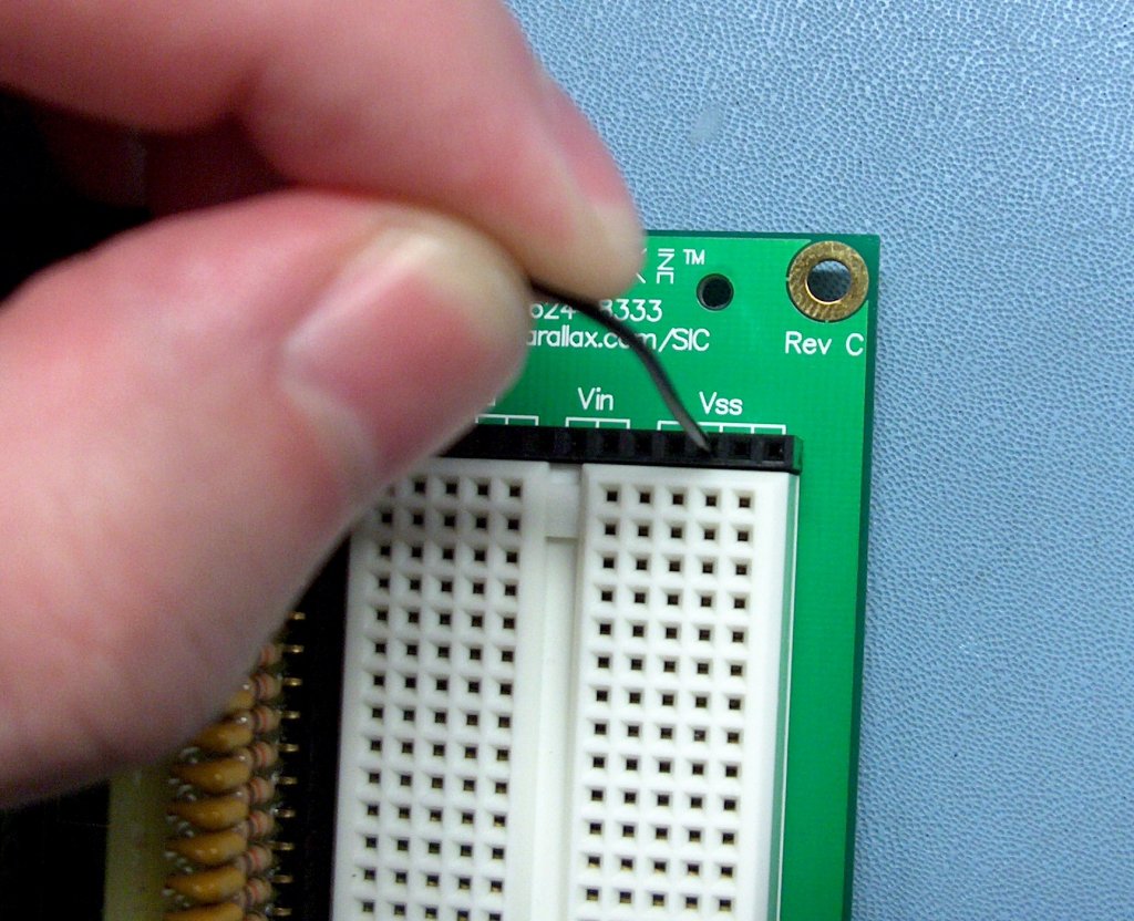

The Card Tester plugs in to the I/O socket connecting to all 16 I/O pins. If you installed the optional grounding wire you can connect it to the VSS connection on the board. Now the HomeWork Board is ready for testing. For those wondering about the built-in series resistors on the Homework Board, they do not affect the overall resistance in the RC circuit enough to affect the test results adversely.
Resources
This project was published in the June 2014 issue of Nuts & Volts Magazine – External Link

BASIC Stamp Module Tester by Chris Savage is licensed under CC BY 4.0![]()
![]()
